
| Home | Products | Networked Robots | Blog | Software | Applications | Contact | View Cart |
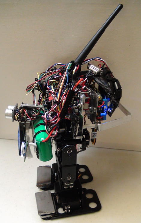
Humanoid (BRAT Based) with I2C Servos and Wireless TCP/IP Conrtrol
 |
 |
 |
|---|
Introduction
The video links below demonstrate the control of BRAT Biped Humanoid by a Java Application via Wireless TCP-IP.
The BRAT Biped Humanoid has 6 PWM Servos. In the design by IONOTRONICS, they are controlled using PIC16F1825 I2C PWM Slaves (MK-24316). A PIC16F1947 is the I2C Master. It receives commands for the I2C based PWM Servos from the Java Application via the Wireless TCP/IP link. In some of the Videos (BRAT Getting Up), the Java Application is running in autonomous mode where it is continuously checking the status of the accelerometers. Based on the reading, it determines whether the BRAT is on its back or standing. If it is on its back, it sends servo commands for the BRAT to get up. If the BRAT is put on its back, it will detect it and get up. The key is that the code providing the intelligence is written in Java with the full powers of Java and speed of a multi-GHz clocked CPU. The BRAT has a PIC16F1947 which has remote control firmware. It provides the status of all sensors to the Java application. It receives servo position, and time to move, commands from the Java Application via Wireless TCP/IP. The PIC16F1947 also has GPIO to control, for example an RGB LED, for status (e.g. Green LED for Standing and Red for when the BRAT is on its back). The Videos demonstrate these capabilities. All code for the Java Application and PIC16F1947 firmware are available as Open Source.
BRAT Humanoid Videos
Item |
Description | Video |
|---|---|---|
1 |
Autonomous Wireless Java Control of BRAT for Getting Up with Accelerometer Sensors. Java Robotics App |  |
2 |
BRAT Wireless Pivot and Turn 45 Degrees (From Sequence File through Wireless TCP/IP). Java Robotics App | |
3 |
BRAT Walking Wireless TCP/IP from Sequence File via Java Robotics App | |
I2C Servo Based BRAT Electronics Schematic
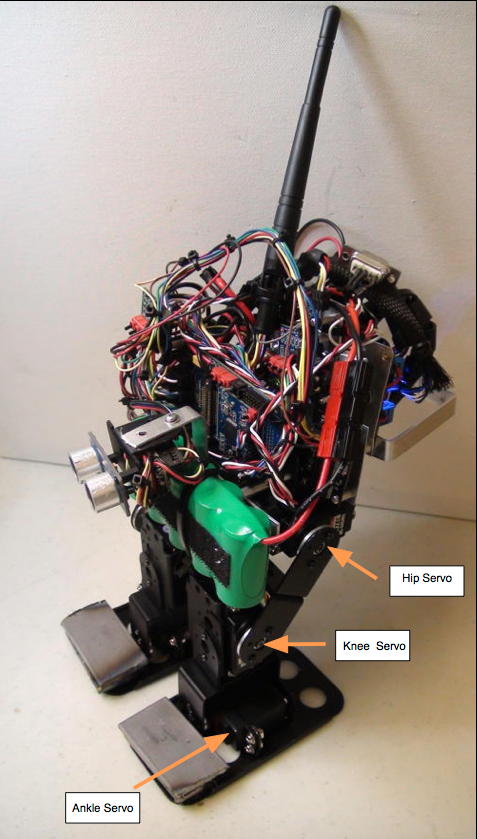
The BRAT with no Electronics forms the basis of the Humanoid Biped Robot Structure. We highly recommend using the 645 Servo Upgrade. Furthermore, as shown in the Photos of the I2C Based BRAT we use a 6V NiMH 2400mAH Battery Pack . We also highly recommend using the 15 Amp PowerPole Connectors with 14 Gauge Wire for the battery. These add weight and bulk but you will be connecting and disconnecting to charge the battery. Also always important to quickly disconnect a battery.
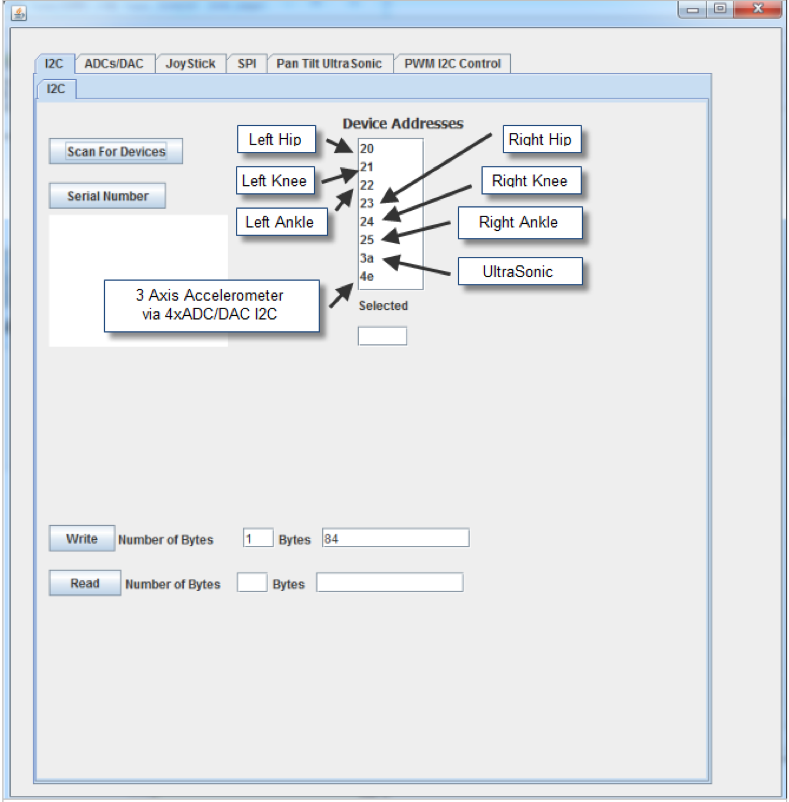
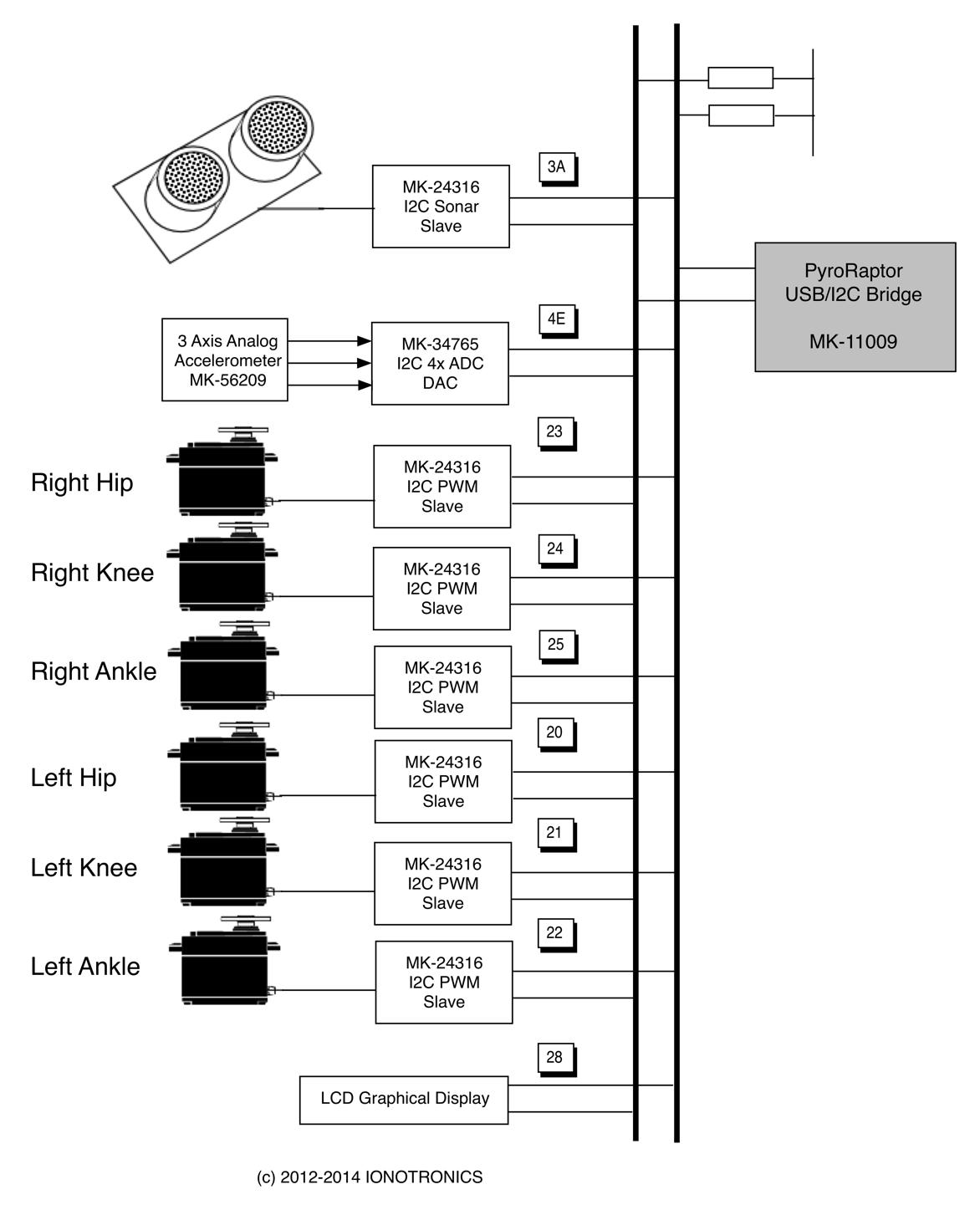
The Figure below shows a scan of the I2C bus of the I2C BRAT showing both the I2C PWM Servos and the Ultrasonic Sensor ( also I2C Slave through using the PIC16F1825 MK-24316). In addition, we have an Analog 3-Axis Accelerometer that is connected to the I2C 4 channel ADC/DAC. This way the accelerometer measurements can be read through the I2C bus. We use the readings from the accelerometer in order to figure out the BRAT's position ( standing, on its back or side etc). The I2C LCD Graphical Display, although power hungry and large, provides the BRAT with the means to communicate. For example, Ultrasonic object distance readings can be shown on the Display as well as messages from the Remote Controller. Also great for code debug. So there is challange to get all this gear onto the BRAT and have it walk, pivot and getup when on its back. But this has been accomplished with even more electronics on the BRAT.
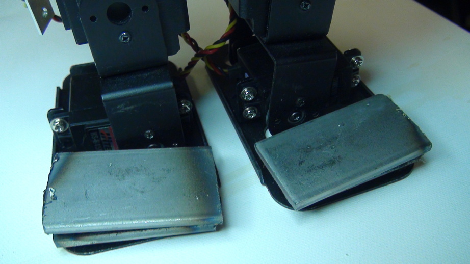
One innovation is to distribute the PIC16F1985's by mounting them on the Servos ( this is why it is small compact device). Also the Batteries can be carried on the Ankles. The BRAT in this design has all the PIC16F1825's on the "backpack".
| I2C Scan | BRAT Servo Identification | |
|---|---|---|
 |
 |
 |
I2C Bus Architecture
The Figure below shows the I2C Bus Architecture for the I2C BRAT. Note that we are showing the Pyroraptor USB/I2C Bridge as the Master. It is a great device to access each I2C devices individually and test it. For example, using the Java Pyroraptor Graphical Interface Tool, we can individually address and control each Joints Servo as we build the I2C BRAT, as well as test the sensors and LCD display. The Java Pyroraptor Grahical Interface Tool has TABS for each device test (PWM Servo,Ultrasonic Sensor, ADC/DAC etc). In the BRAT, the I2C Master is the PIC16F1947. We can always disconnect it and use the Pyroraptor to test. We can also use a 32 bit PIC instead of the 8 bit PIC. There are great advantages with the 8 bit PIC in terms of power consumption. Also, there are preferences for the C Code Development environment depending on comfort level and experience as well as other factors.
I2C PWM Slaves for the Joints
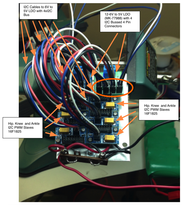
The Labeled Photo below shows the construction of a plate housing the six I2C PWM Slaves that control the six BRAT Servos (Left Hip, Knee and Ankle and Right Hip, Knee and Ankle). Each I2C PWM Slave is based on a PIC16F1825. The board contains a 4 pin Hirose connector for connecting to the I2C bus (also to power the device). The 16 pin Hirose DF-11 Series connector is used to provide the PWM signal to the servo. Each I2C PWM Slave can be programmed with different I2C address which is stored in EEPROM ( use the Pyroraptor and the Java Pyroraptor Graphical User Interface). In this design all I2C PWM Slaves are mounted to the back of the BRAT. However, another design approach is to place each I2C PWM Slave on a servo and distribute the load. IONOTRONICS provides a file to 3D print the part to attach the I2C PWM Slave to the Servo. A nice cabeling system can be used to cable each I2C PWM Slave and Servo to the I2C bus and 6V power supply ( for the servo).
I2C Ultrasonic Slave
The I2C BRAT has an Ultrasonic Sensor. A PIC16F1825 is used to convert the Paralex Ultra Sonic Sensor to an I2C Slave Device. The PIC16F194 can instruct the I2C Ultrasonic slave to make a measurement of distance to an obstacle or object. The measurement is a 16 bit number. For details on the PIC16F1985 based I2C ULtrasonic Sensor see the detailed description and Videos at this link. Using the debounce switches we can configure the I2C BRAT to do a continuous scan and display the distance to an object on the LCD display.
Embedded Processor and Robotics Platform
To control the I2C BRAT we use the PIC16F1947 8-bit embedded processor. It is mated to the Eoraptor Robotics Platform. The PIC16F1947 runs the RRCP for remote(TCP/IP) or local RS-232 connections for Robotics Control and Sensor Measurements as well as other capabilities. We also add Wireless TCP/IP support by mnating the WiFi Adaptor module to the Eoraptor. The Eoraptor provides multiple 12 pin Hirose DF-11 Series connectors for the PIC16F1947 GPIO signals. Some GPIO are connected to the Four Debounce Switch and LED module. The switch settings provide the RRCP running on the PIC16F1947 with test modes. One test mode is a local continuous test of the Ultrasonic sensor where the distance to an object is displayed on the LCD as the device continously scans. The Blue, Green, Red and Yellow LEDS on the Debouce Switch LED Board are used for startup tests (blinking LEDs) as well as self tests. See the RRCP page for details on the self test. See the PIC16F1947 User Guide on how to connect the Debouce Switch LED to the Eoraptor.
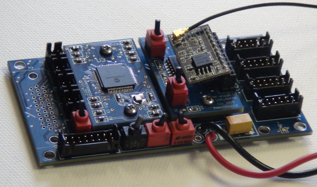
PIC16F1947 Adaptor and WiFi Adaptor Mated to Euroraptor Robotics Control Platform With Configuration Switches
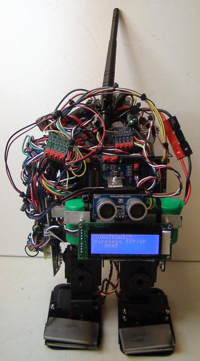
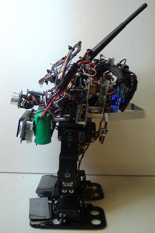
The Photo Shows the PIC16F1947 and Euroraptor Mounted on the BRAT. Also the 4xDebounce Switch and LED Modules
Building an I2C BRAT |
 |
The I2C Rover can be built using the parts and suggestions in the Table below. Note the either the 32 bit PIC ( MK-33856) or 8 bit PIC (MK-28988) can be used.
To build the I2C Rover you will need:
Item |
Description | Part Number | Notes | |
|---|---|---|---|---|
1 |
BRAT from Lynxmotion ( No Electronics) | BRAT No Electronics | Do not use the Hitech 422 Servos. See upgrade below. | |
2 |
645 Servo Upgrade | Model Number: BRAT-645 | Worth it | |
3 |
6x PIC16F1825 I2C PWM Controller | MK-24316 | Converts Servos to I2C Slaves for PWM Control See the |
|
4 |
2x 12-6 Volt input 5V LDO 4xI2C Bus | MK-77988 | Provides Four I2C Bussed 4 Pin Connectors. Two Modules needed to Support 6 I2C Servos | |
5 |
I2C Bus 3.3V and 5V with Volatge Regulators 12V-6V input. | MK-33910 | Provides main I2C Bus and is driven by PIC16F1947 I2C Master. Supports both 3.3V and 5V I2C Devices | |
6 |
PIC16F1947 Processor Adaptor | MK-28988 | Main Embedded Processor for Robot Control with RRCP | |
7 |
Eoraptor Robotics Control Platform | MK-36019 | Provides Embedded Procesor with I2C Support, UART Support, Wireless, GPIO Connectors and SPI EEPROM | |
8 |
WiFi RS-232 Adaptor | MK-60689 | Provides Wireless TCP/IP connection to Embedded Processor Through Serial UART. | |
9 |
3 Axis Analog Accelerometer | MK-56209 | Provides 3 Axis Analog Accelerometer to Support BRAT Position Determination (UP, on Back, on Side etc). Interfaced to I2C Through 4 Channel ADC/DAC | |
10 |
4 Channel ADC and DAC | MK-55856 | 4 ADC Channels for Analog Accelerometer or Infrared Sensors. I2C Address 0x4E | |
11 |
Four Debounced Switches and Four LEDS (Red, Green, Blue, Yellow) | MK-55856 | Used to Put Rover in Various Modes Including Remote Wireless or RS-232 Control and Local Test Modes. LEDs Used for Self Test on Startup (Reset) | |
12 |
Various Cables for Hirose DF-11 Series Connectors and 4 Pin, 12 Pin and 16 Pin Headers | MK-32642 | The Kit Allows for Various Cable Combinations. You will need 12 pin to 12 pin, 4 pin to 4 pin etc. | |
13 |
Programming Cable for PIC32 ( ICD-64 or PicKit3 Support). | This is a Cable with 16 pin DF-11 Hirose Header on One Side and 6 Pin Molex on Other Side. Needed only if firmware change required. PIC16F1825 shipped with firmware. | ||
14 |
Graphic LCD Display I2C Support. Connects to 5V I2C Bus | GLK12232A-25-SM-GW-VS | I2C Graphical LCD Display | |
15 |
PowerPole Wires, Connectors and Fuses plus Wires (Black and Red 14 Gauge) | Anderson Powerpole Connectors | Use 15 Amp Red/Black Powerpole Connectors, Retention Clips etc. | |
16 |
Batteries | 6V Ni-MH 2800mAh Battery Pack | Use One. Use Power Switch. Design a Cable to Adapt Battery to Powerpole. |
In addition to the above you will need:
Item |
Description | Part | Notes | |
1 |
This is the 2-56 screw used to attach the PCB to spacer | Machine Screw Pan Phillips 2-56 | Top Side of Plexiglas PCB to Spacer | |
2 |
The 3/8" #2-56 Standoff | Round Standoff Threaded #2-56 Aluminum 0.375" (9.53mm) 3/8" | Spacer | |
Photos
 |
 |
